Demonstrations

Physics demonstrations for all.

Tensegrity Explained

There is a new internet trend called “tensegrity” – an amalgamation of the words tension and integrity. It is basically a trend of videos showing how objects appear to float above a structure while experiencing tensions that appear to pull parts of the floating object downwards.

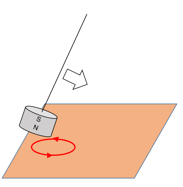
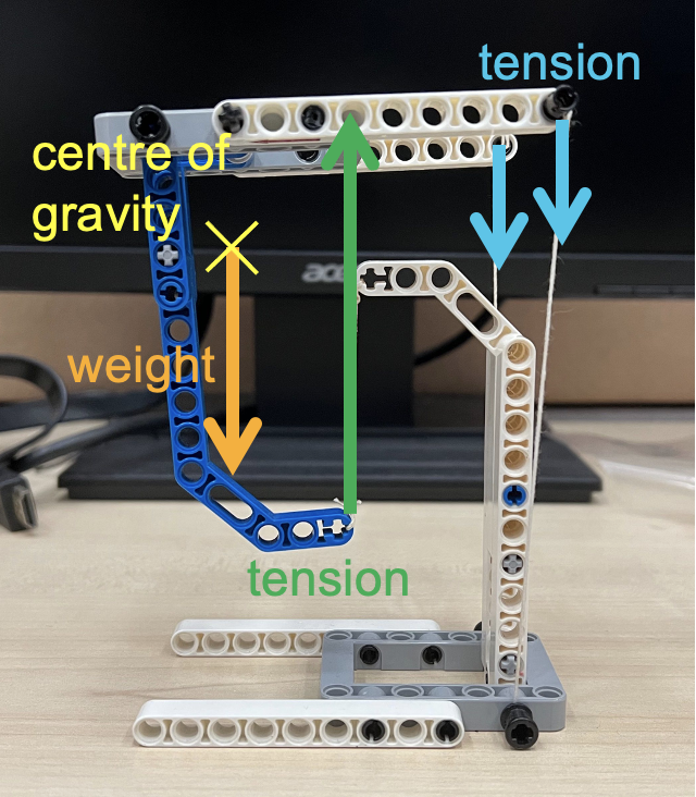
In the diagram below, the red vectors show the tensions acting on the “floating” object while the green vector shows the weight of the object.

The main force that makes this possible is the upward tension (shown below) exerted by the string from which the lowest point of the object is suspended. The other tensions are downward and serve to balance the moment created by the weight of the object. The centre of gravity of the “floating” structure lies just in front of the supporting string. The two smaller downward vectors at the back due to the strings balance the moment due to the weight, and give the structure stability sideways.

This is a fun demonstration to teach the principle of moments, and concepts of equilibrium.

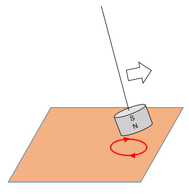
The next image labels the forces acting on the upper structure. Notice that the centre of gravity lies somewhere in empty space due to its shape.

Only the forces acting on the upper half of the structure are drawn in this image to illustrate why it is able to remain in equilibrium

These tensegrity structures are very easy to build if you understand the physics behind them. Some tips on building such structures:

  1. Make the two strings exerting the downward tensions are easy to adjust by using technic pins to stick them into bricks with holes. You can simply pull to release more string in order to achieve the right balance.
  2. The two strings should be sufficiently far apart to prevent the floating structure from tilting too easily to the side.
  3. The centre of gravity of the floating structure must be in front of the string exerting the upward tension.
  4. The base must be wide enough to provide some stability so that the whole structure does not topple.

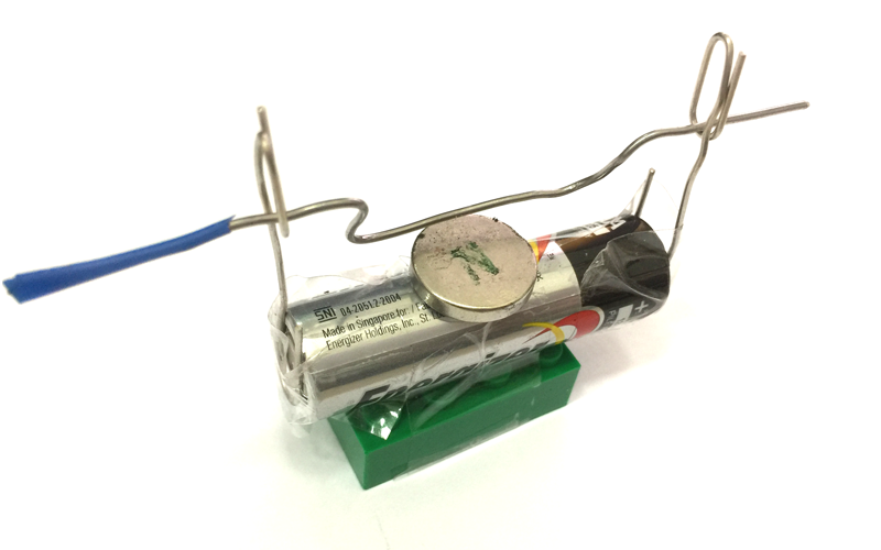
Here’s another tensegrity structure that I built: this time, with a Lego construction theme.

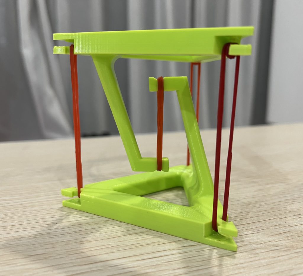
Apart from using Lego, I have also 3D-printed a tensegrity structure that only requires rubber bands to hold up. In this case, the centre of gravity of the upper structure is somewhere more central with respect to the base structure. Hence, 3 rubber bands of almost equal tension will be used to provide the balance. The STL file for the 3D model can be downloaded from Thingiverse.com.

The main challenge in assembling a tensegrity structure is the adjustment of the tensions such that the upper structure is balanced. One way to simplify that, for beginners, is to use one that is supported by rubber bands as the rubber bands can adjust their lengths according to the tensions required.

3D-printed tensegrity table balanced by rubber bands

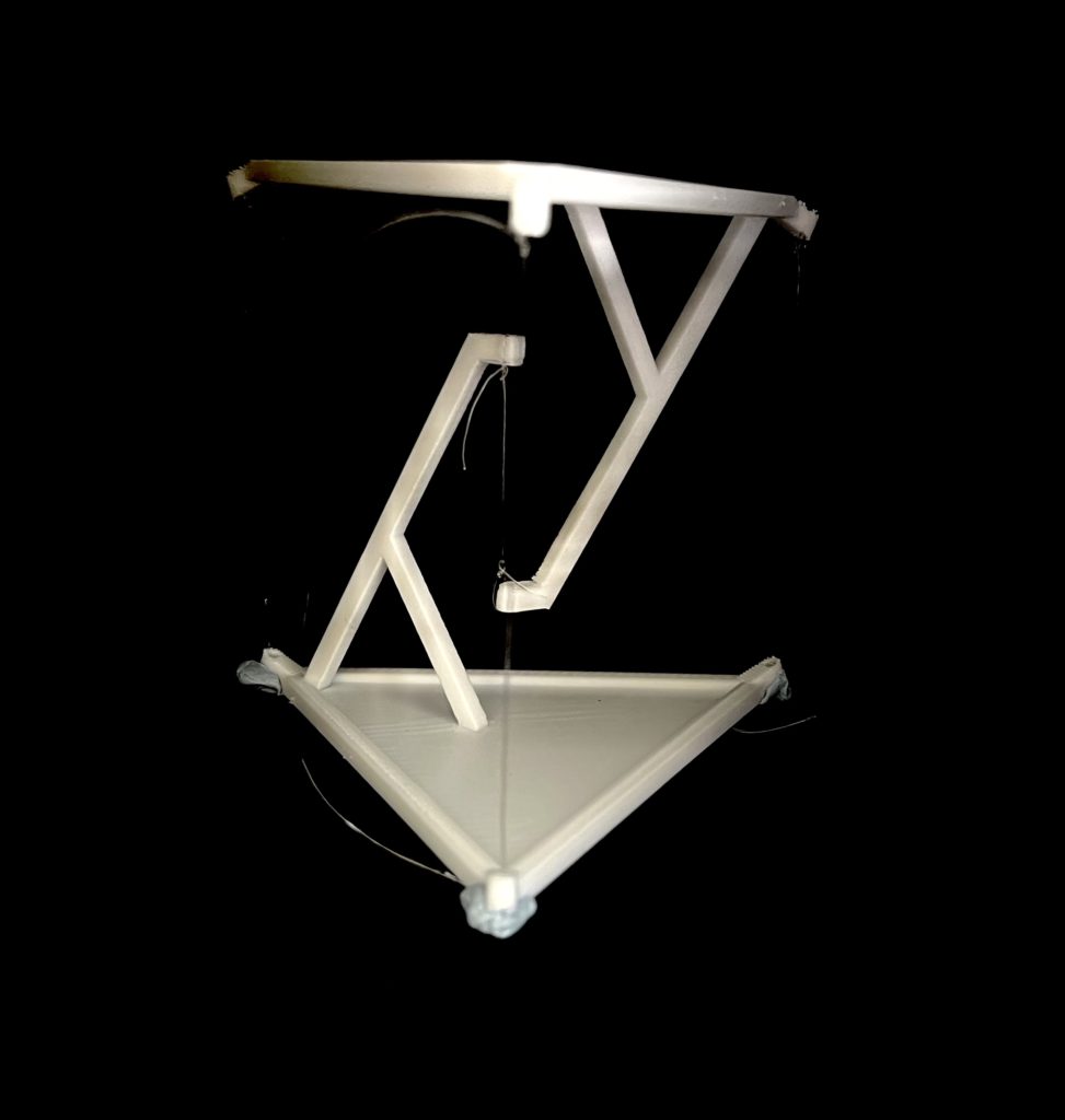
Another tip is to use some blu-tack instead of tying the knots dead such as in the photo below. This is a 3D printed structure, also from Thingiverse.

3D-printed tensegrity table held up and balanced by nylon string

(This post was first published on 18 April 2020 and is revised on 24 August 2022.)

Braking of a Magnetic Pendulum with Copper Plate

In this video, we will observe how induced eddy currents in a copper plate slow down a magnetic pendulum. 

When the pendulum is set in motion, it usually oscillates for quite a while. This pendulum consists of a strong magnet.

If we slide a copper plate underneath the magnet while it is in motion, the magnet comes to a stop quickly. Note that copper is not a ferromagnetic material, which means it does not get attracted to a stationary magnet.

As the magnet moves across an area on the copper plate, the change in magnetic flux induces eddy currents on the plate. These eddy currents flow in such a way as to repel the magnet as it approaches the plate and attracts the magnet as it leaves the plate, therefore slowing the magnetic pendulum.

Eddy currents repels the magnet as it approaches
Eddy currents attracts the magnet as it leaves

When we pull the copper sheet out from under a stationary magnetic pendulum, the eddy currents will flow in such a way that it becomes attracted to the copper sheet.

Moving the copper sheet to and fro at a certain frequency (the pendulum’s natural frequency), the magnetic pendulum can be made to oscillate again.

Non-Uniform Vertical Circular Motion

Using a chain of rubber bands, I swung a ball around in a vertical loop. This demonstration shows how the tension in an elastic band changes according to the position of the ball, by referring to the length of the elastic band.

Securing the elastic band to the ball with a shoelace

When the ball of mass $m$ is at the bottom of the loop, the centripetal force is given by the difference between tension $T_{bottom}$ and weight $mg$, where $T_{bottom}$ varies depending on the speed of the ball $v_{bottom}$ and the radius of the curvature $r_{bottom}$.

$T_{bottom} – mg = \dfrac{mv_{bottom}^2}{r_{bottom}}$

When the ball is at the top of the path, it is given by

$T_{top} + mg = \dfrac{mv_{top}^2}{r_{top}}$

As the weight is acting in the same direction to tension when the ball is at the top, a smaller tension is exerted by the elastic band to maintain a centripetal force. Therefore , $T_{bottom} > T_{top}$.

The GeoGebra app below shows a simpler version of a vertical loop – a circular path with a fixed radius $r$. Consider a ball sliding around a smooth circular loop. The normal contact force varies such that

$N_{bottom} = \dfrac{mv_{bottom}^2}{r} + mg$

$N_{top} = \dfrac{mv_{top}^2}{r} – mg$

It can be shown that the minimum height at which the ball must be released in order for it to complete the loop without losing contact with the track is 2.5 times the radius of the frictionless circular track.

If we were to consider the rotational kinetic energy required for the ball to roll, the required initial height will have to be 2.7 times the radius, as shown in the video below:

Many thanks to Dr Darren Tan for his input. Do check out his EJSS simulation of a mass-spring motion in a vertical plane, which comes with many more features such as the ability to vary the initial velocity of the mass, graphs showing the variation of energy and velocity, as well as an option for a mass-string motion as well.

Measuring speed of sound in air using Audacity

A physics demonstration on how to measure the speed of sound in air using Audacity, an open source audio recording software. There are Windows and Mac versions of this free software, and even a portable version that can run off a flash drive without needing to be installed on a computer (for school systems with stricter measures regarding installing of software).

The sound is reflected along a long hollow tube that somehow, existed in our school’s laboratory. The two sound signals were picked up using a clip-on microphone attached to the open end of the tube and plugged into the laptop. I used my son’s castanet which gives a crisp sound and hence, a simple waveform that will not have the echo overlapping with the generated sound. The timing at which the sound signals were first detected were read and subtracted to obtain the time taken for the wave to travel up and down the 237 cm tube.

The value of the speed of sound calculated is 356 m/s, which is a bit on the high side due to the temperature of 35°C and relative humidity of between 60-95% when the reading was carried out.

If you are interested, you can check out how the software can be used to determine the frequency of a tuning fork.

Magnetic Force on a Current-Carrying Conductor

Using a neodymium magnet, some paper clips and a battery, you can demonstrate the magnetic force acting on a current-carrying wire while recalling Fleming’s left-hand rule. Using the same frame constructed in the previous video, you just need to add a wire with a few bends in between to create a U-shape in the middle as shown in the picture below. A small piece of insulating tape (you can use any adhesive tape) is added to one end of the wire to show the original dangling position of the U-shape before current flows through it. Be sure to leave some space at the end with the insulating tape for you to switch on and off the current by pushing that end in and out.

With the south pole facing up and the current flowing from right to left, the magnetic force acts towards you.

When the insulating tape touches the paper clip, current stops flowing and there is no magnetic force.

With the south pole facing up and the current flowing from right to left, the magnetic force acts away from you.