Seng Kwang Tan

Relative Velocity Simulation

0 m/s

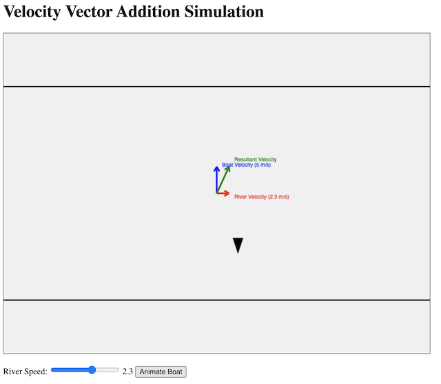
In yet another demonstration of ChatGPT 4o’s capabilities, I generated the above simulation app without writing a single line of code myself: https://physicstjc.github.io/sls/relative-velocity/index.html

The process took 4 prompts.

Prompt 1: Create a javascript simulation in a single html file that demonstrates the addition of two velocity vectors to give a resultant velocity. The velocity of a boat travelling in still water moving across a river is shown as vertically upward. A slider will change the speed and direction of the water flow. The velocity of the river water is also shown. Finally, show the addition of the two vectors to give a third vector: the resultant velocity. Create a button for animating the boat’s movement.

Response: Here’s an HTML file with embedded JavaScript to create a simulation of the addition of two velocity vectors. This simulation includes a slider to adjust the speed and direction of the river flow, and a button to animate the boat’s movement. (Code is not included to avoid making this post too long.)

Prompt 2: Use two horizontal lines to show the shores of the river, also the starting and ending point of the boat’s journey. The boat should be represented with a pencil-like shape, moving upward from one horizontal line to another. The boat should be moving in the direction of the resultant velocity. The vectors should be represented with arrows, not just lines.

Response: Here’s the updated HTML file with the specified features:

Two horizontal lines representing the shores of the river.
A pencil-like shape representing the boat, moving from one shore to the other in the direction of the resultant velocity.
Arrows to represent the vectors.

Prompt 3: Very good! Now invert the shape of the boat vertically. Also, draw some light blue wavy curves between the two horizontal lines that are stationary when the river speed is zero but move at the river velocity otherwise.

Response: Here’s the updated HTML file with the specified changes:

The boat shape is inverted vertically.
Light blue wavy curves are drawn between the two horizontal lines to represent the river water. These waves are stationary when the river speed is zero but move at the river velocity otherwise.

Prompt 4: Keep the canvas to 640 pixels wide and 480 pixels tall. Resize everything else accordingly.

And what you see in the beginning of this post was the result.

Radioactive Decay Simulation Created Using ChatGPT 4o


This simulation of radioactive decay was created using ChatGPT4o.

The prompts used are:

  • Create a javascript simulation with a html5 canvas. Show all the codes in one page.
  • Start with grey particles in a 60 by 60 arrangement. Represent the particles using small circles.
  • Upon clicking the start animation button, every second, a number of grey particles will turn red. Randomly select the particles to decay. Assume the half-life to be one second initially. Allow the user to change the half life from one to 200 seconds. The particles that have turned red must remain red.
  • Use plotly.js to create a decay graph. The horizontal axis is time and vertical axis is number of undecayed nuclei.
  • Initialise the graph such that the time axis starts at zero and the vertical axis shows 3600 at first.
  • Refresh the particles and the graph every second.
  • Display the numerical value of time and number of undecayed particles in text as well.
  • Add a button to download the data in csv format.

Radioactive decay is a fundamental process in nuclear physics where unstable atomic nuclei lose energy by emitting radiation. This decay occurs randomly for individual atoms, but when observed in a large sample, it follows a predictable statistical pattern described by the half-life, which is the time required for half of the radioactive nuclei in a sample to decay. The half-life is a constant characteristic of each radioactive isotope and is not affected by physical conditions such as temperature or pressure.

The probability of decay for each nucleus per unit time is constant, leading to an exponential decay law. Mathematically, if $N_O$​ is the initial number of undecayed nuclei, the number remaining at time 𝑡t can be described by $N(t) = N_0 \dot (0.5)^{t/T_{1/2}}$, where $T_{1/2}$​ is the half-life. This exponential relationship explains why, after each half-life, half of the remaining radioactive atoms will have decayed. As a result, the decay process continues until all the radioactive material has transformed into stable isotopes.

In our simulation, we model this stochastic process by randomly determining whether each nucleus decays based on the given half-life. Each second, a fraction of the remaining grey particles (representing undecayed nuclei) turn red (representing decayed nuclei), mimicking the random yet statistically predictable nature of radioactive decay. The simulation and accompanying graph provide a visual and quantitative representation of how radioactive substances diminish over time, illustrating the principles of exponential decay and the role of half-life in nuclear physics.

Manometer Simulation using GeoGebra

After trying to create a javascript simulation for the manometer using ChatGPT, I decided to return to GeoGebra, a platform that I am more used to, to create this interactive with more customisation. It comes with a ruler and a self-assessment feature for students to key in the value of pressure.

https://www.geogebra.org/m/qyuncz3h

A U-tube manometer is a fundamental device used to measure pressure differences in fluid systems with simplicity and precision. It consists of a U-shaped tube typically made from transparent glass or plastic, allowing for clear observation of fluid levels within the tube. The tube is partially filled with a manometric fluid such as mercury or water, chosen based on the expected pressure range and application. The manometer has a graduated scale for measuring the height difference between the fluid levels in the two arms of the U-tube. The device is connected at two points where the pressure difference needs to be assessed, such as in gas pipelines, liquid tanks, or other systems requiring pressure monitoring.

When the manometer is connected to the pressure sources, the fluid within the U-tube will adjust its levels until equilibrium is achieved, with one side rising and the other side falling. The difference in height between the two columns of fluid (h) indicates the pressure difference. This difference is read using the graduated scale and is used to calculate the pressure difference (ΔP) with the formula ΔP = ρgh, where ρ is the density of the manometric fluid, and g is the acceleration due to gravity.

U-tube Manometer – a ChatGPT-Generated Simulation

I wanted a simple manometer simulation for the Sec 3 topic of Pressure and decided to try generating one with ChatGPT3.5. The first attempt, using just words, resulted in many errors such as single lines instead of 2D objects being used to represent the tubes and coloured bars that move in the wrong direction.

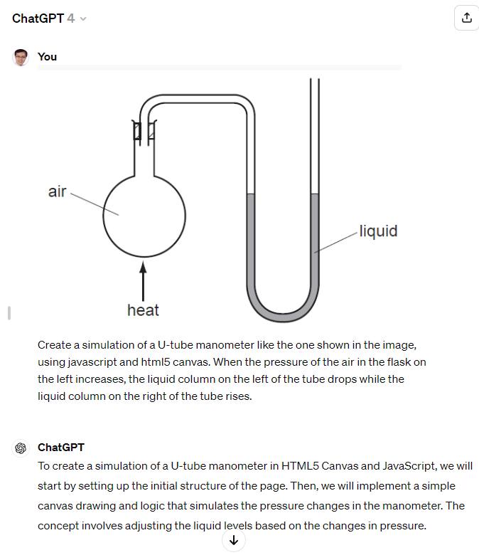
However, after I switched to ChatGPT4 and uploaded an image for reference, it was then able to produce a proper design consisting of glass tubes and coloured columns that move up and down with pressure changes in a flask. With a bit of UI changes using further prompts, this was the final product.


Link

The following is the screenshot showing the image that was uploaded as well as the initial prompt.

A little experiment with an AI chatbot

I built a customised AI chatbot using OpenAI’s API, which could run on GPT3.5 or GPT4 and used it to facilitate socratic questioning for students to arrive at the correct answer to a commonly misunderstood Physics concept. The process was not too complicated. One would need a OpenAI developer account to obtain the API key, and a Streamlit account to deploy the app. To input the API key, update the settings of the Streamlit app with this line: OPENAI_API_KEY=”{key}”. The codes can be forked from here.

This video shows a simulation of the interaction that I had with it.

I also stored the interactions that my students had with the bot in csv format, saved in an AWS S3 bucket.

Here are some samples, in which you can see the system prompt given: Speak like a teacher who assesses the response of the student based on clarity, precision, accuracy, logic, relevance and significance. Help the user get to the answer by asking guiding questions to scaffold the learning. The question is: Two balls are placed at the back of a truck that is moving at constant velocity. The blue ball is twice the mass of the red ball. The floor of the truck is perfectly smooth. Compare the movement of the two balls when the truck comes to an abrupt stop. The success criteria for the user is to be able to explain that both balls will move at the same speed once the truck comes to an abrupt stop, according to Newton’s first law, since there will be no net force acting on them since the floor of the truck is smooth and there is no friction.

It was rather entertaining for the students as some of them tried to trick the bot to giving them the answers. I did a pre-test for this question before the test and only 3-5% of the students in both classes got the answer correct but almost all of them (ascertained by an informal poll) knew the correct answer after going through the discussion with the bot.

I hope to continue experimenting with variations of the system prompts when I have time. However, it’s back to marking and preparing for staff PD now!

Analogue Meter Template

This GeoGebra applet (https://www.geogebra.org/m/watavkq8) can serve as a template for an analogue meter.

I added a check for the text input so that users have to key in the correct number of decimal places according to the precision of the instrument. For instance, a reading of 1 V should be recorded as 1.00 V and 1.5 V recorded as 1.50 V. Users need to read to half the smallest division, e.g. if the needle is between 2.4 and 2.5, they should input 2.45 V.