Seng Kwang Tan

Planning Question

The following is the script that I used for recording the video above for our e-learning day. I’m posting it here as I can edit it easily via wordpress’s mobile app, and because I have LaTeX enabled here.

Aim:

The aim of this planning question is to investigate how the resonant frequency of a wire vibrating in its fundamental mode depends on the tension in the wire.

The independent variable is the tension in the string which can be varied by hanging masses at one end of the wire and dangling that end over the edge of a table on a pulley. The tension is represented by the symbol.

The dependent variable is the resonant frequency of the fundamental mode in the wire. The fundamental mode consists of two nodes at both ends of the wire and one antinode in the middle.

In other words, in our experiment, we shall vary tension and measure the resonant frequency of the fundamental mode.

The length of wire between the supports is kept constant throughout the experiment and we shall use the same wire throughout so that the mass per unit length is kept constant.

Procedure:

The experiment will be set up according to this diagram. One end of the wire is first tied to a fixed object. The other end is hanging over a pulley clamped on the edge of the laboratory table and tied to a mass hanger. To control the length of the wire, place a bridge at each end. Only the length of the wire between the two bridges will be vibrating. We shall keep this length constant for the whole experiment.

Record the mass of the mass hanger m and determine its weight. The weight mg is taken to be equal to the tension T on the string.

A uniform horizontal magnetic field is generated by a pair of large electromagnetic coils on both sides of the wire. The wire is connected on both ends to a function generator. An alternating current is produced by the function generator and its frequency can be varied using the same apparatus. The function generator should have a display that enables us to read the frequency. 

The resulting magnetic force acting on the wire will be driving the oscillation of the wire at the frequency shown on the function generator. By adjusting the frequency of the alternating current until the fundamental mode of a standing wave is formed on the wire, we can record the resonant frequency ffor the corresponding tension T.

We shall repeat the experiment for different values of m by adding known amounts of mass (e.g. 50 g increments each time) onto the mass hanger. All the values for the mass m and resonant frequency for the fundamental modes fo should be recorded and tabulated.

The tension in the wire is then calculated using the equation T = mg.

Assume that the resonant frequency for the fundamental mode fo and the tension T follows the equation  fo = kTn where k and n are constants. Then lg fo = lg k + n lg T. Plotting a graph of lg fo versus lg T, we can conclude that the assumption is correct if a linear relationship is observed and we can obtain the values of n and k from the gradient and the vertical intercept of the graph respectively.

As a safety consideration, the person conducting the experiment should wear goggles as the wire at high tension might suddenly snap or come loose. Always handle power supply with care.

As a precaution to improve reliabiliy, we can place a white card behind the vibrating wire so it can be seen easily. To make sure that the weight of each of the slotted masses is as indicated, measure them on a weighing balance. FInally, ensure that the pulley is smooth by measuring the tension in the wire using a force meter to check that it is indeed equal to the weight of the slotted mass.
Boyle’s Law

Using a hand-operated vacuum pump, we can demonstrate the relationship between pressure and volume of a gas. According to Boyle’s law, the pressure of a gas of constant mass and temperature will be inversely proportional to its volume.

In our demonstration, we will reduce the ambient pressure within the sealed container, hence allowing the higher internal pressure of a balloon to cause it to expand. When the volume within the balloon increases, the internal pressure can be observed to decrease until it is in equilibrium with the surrounding pressure.

While the relationship between pressure and volume is not exactly obeying Boyle’s law due to additional factors such as the tension due to the elastic property of the balloon, it does demonstrate an inverse relationship.

Polarization with 3 Filters

In what seems like a counter-intuitive demonstration, we can place a polarizing filter in between two other filters which do not transmit light in order to cause light to pass through again.

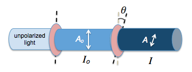
This is because each filter will permit the components of electric field vectors of the electromagnetic waves that are parallel to its axis of polarization according to the equation $$A = A_o \cos{\theta}$$ where $A_o$ is the original amplitude of the unpolarized wave incident on the filter and $\theta$ is the angle between the electric field vector and the axis of polarization. Each time the wave passes through a filter, it undergoes a reduction in amplitude according to the equation so that by the third filter, its resultant amplitude is
$$A = A_o \cos{\theta_1} \cos{\theta_2}$$
where $\theta_i$ is the angle between the axis of polarization of the ith filter and the electric field vector direction of the incident light on the ith filter.

According to Malus’ law, the intensity of the light that passes through these two filters is given by

$$I=I_o\cos^2\theta$$

where I0 is the initial intensity and θ is the angle between the light’s initial polarization direction and the axis of the polarizer.

The resulting intensity for light that passes through 3 filters is given by

$$I=I_o \cos^2{\theta_1}\cos^2{\theta_2}$$

where $\theta_1$ is the angle between the axes of the first and second filters and $theta_2$ is the angle between the axes of the second and third filters.

Polarization Using Sunglasses and a Computer Screen

Using a pair of polarizing sunglasses, you can demonstrate the effects of polarization together with a computer screen which is also polarizing. When the axes of polarization of the two polarizing screens are rotated, the brightness alternates between bright and dark.

Light coming from a computer screen is usually polarized. In the video below, when polarized light passes through another polarizer, the intensity of the light is given by Malus’ law:

$$I = I_o cos ^2{\theta}$$

where $$\theta$$ is the angle between the two axes of polarization and $$I_o$$ is the original intensity of the unpolarized light.

Only the components of electric field vectors in electromagnetic radiation that are parallel to the axis of polarization of a polarizing filter will be permitted through. Those electric field components that are perpendicular to the polarization axis are blocked by the filter.

malus-law

Hence, the amplitude of a vector A that passes through is given by $$A = A_o \cos{\theta}$$. Since intensity is proportional to the square of amplitude ($$ I \propto {A^2}$$), we have Malus’ law.

The purpose of having polarizing filters in sunglasses and computer screens is to cut out glare due to light from other sources.

Learning about Sound with Audacity

Audacity is a free audio recording and editing software downloadable from http://audacity.sourceforge.net. It is cross-platform meaning you can run it on PC or Mac.

Once you have the software installed, you can try out some of its simpler functions, such as recording and playing back. You can also generate tones of known frequencies, which will be useful for experiments such as using stationary waves to determine the speed of sound in air.

Frequency and pitch

The first activity serves as an introduction to the software and can be easily carried out. All you need is a computer with Audacity installed and a microphone connected to it. Tuning forks of different frequencies will be best for this activity because of the simple and pure waveforms generated. A regular wave pattern can also be recorded with the help of a musical instrument such as a guitar or by singing a note.

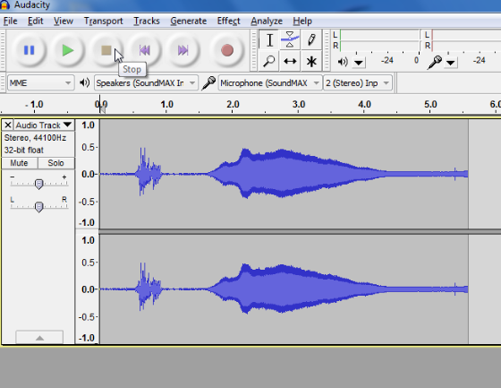
To make a sound with the tuning fork, strike it against something hard such as the heel of your hand. The two prongs of the fork, known as “tines,”  will then vibrate with a fixed frequency, thus generating a waveform with a displacement that is almost sinusoidal. Place this tuning fork next to the microphone and you should see a densely packed waveform like the following:

using-audacity-to-learn-about-sound

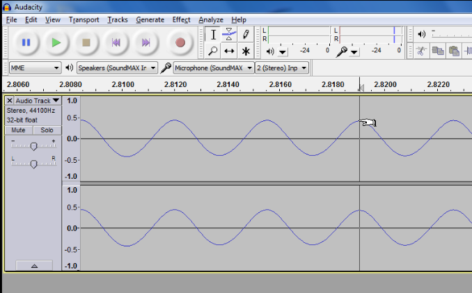
Zoom into the peaks recorded by clicking on the peaks of interest and pressing Ctrl 1 for Windows or Command 1 for Mac. You should observe a repeated pattern in the waveform.

audacity-sound-experiment

By reading off the time difference on the horizontal axis between two peaks, you can measure the period of the wave. Using $$f=\frac{1}{T}$$ where f is the frequency of the wave, and T is the period, you can verify the frequency measured with the known value of the tuning fork’s frequency.

In the above graph, the period is 2.8190-2.8155 = 0.0035s. The frequency of the tuning fork used is given by $$f=\frac{1}{T}=\frac{1}{0.0035}= 286 \text{ Hz}$$ which is roughly that of a D note.

Squishy Circuits

image taken from http://courseweb.stthomas.edu/apthomas/SquishyCircuits/howTo.htm

I came across this Ted video on Squishy Circuits, presented by AnnMarie Thomas from the University of St Thomas and found it to be a suitable activity for kids. I shall attempt to make some when I am free with instructions from the following site:

http://courseweb.stthomas.edu/apthomas/SquishyCircuits/index.htm

Be sure to watch this page for photos and videos!

As I was contemplating the potential of combining conductive and insulating dough to make fun toys with the help of electric motors and the learning that can come from it. Apart from the obvious learning related to electrical resistance and current, we can even learn about flotation and fluid dynamics by building floating boats of different hull shapes.