Using a neodymium magnet, some paper clips and a battery, you can demonstrate the magnetic force acting on a current-carrying wire while recalling Fleming’s left-hand rule. Using the same frame constructed in the previous video, you just need to add a wire with a few bends in between to create a U-shape in the middle as shown in the picture below. A small piece of insulating tape (you can use any adhesive tape) is added to one end of the wire to show the original dangling position of the U-shape before current flows through it. Be sure to leave some space at the end with the insulating tape for you to switch on and off the current by pushing that end in and out.
With the south pole facing up and the current flowing from right to left, the magnetic force acts towards you.When the insulating tape touches the paper clip, current stops flowing and there is no magnetic force.With the south pole facing up and the current flowing from right to left, the magnetic force acts away from you.
Using material that is easily available, you can build a simple homopolar D.C. motor (one that uses a single magnetic pole. I made the video above to help you do so.
The material used are as follows:
insulated copper wire
paper clips
neodymium magnet
1.5V AA battery
plastic or wooden block (I used a 4×2 Lego block)
scissors
permanent marker
adhesive tape
The steps involved are:
Attaching the magnet on the side of the battery using a long piece of adhesive tape and sticking both of them onto the Lego block. The polarity of the magnet does not matter.
Next, we need to shape one end of each paper clip so as to make it longer and to make a small loop at the top. The paper clips are then fixed on the ends of the battery using adhesive tape.
Coiling wire can be done with the help of a round cylindrical object such as a marker. Roughly 10-15 coils will do.
The ends of the wire can used to bundle the coils together. Make sure they are tied up tightly.
Since we are using an insulated wire (otherwise the current will just go straight from one paper clip to another without passing through the coils), we need to scrape of the insulation at the ends using either sandpaper or the edge of a pair of scissors.
Using a permanent marker, we can colour one side each end in order to insulate that side. This will prevent current from flowing through the loops for half of every cycle. It has the same effect as that of a commutator.
Finally, we will mount the coils onto the two paper clips and allow the motor to spin.
Do take note that the motor should not be left connected to the battery for too long as it will drain the battery very quickly and generate a lot of heat in the process.
How this can be used for the O-level/A-level syllabus
Teachers can use this as a demonstration that shows the motor effect of a current in a wire placed in a magnetic field, as well as to apply Fleming’s left-hand rule.
One can also make an second coil without insulating half the surface of the points of contact with the paper clips to show the importance of the commutator in a DC motor. The coil will simply oscillate to and fro due to the change in direction of the magnetic force on the lower half of the loop every half a turn.
I made this rather simple video this morning showing a physics demonstration on the effect of magnetic shielding. A paper clip is shown to be attracted to a magnet. A series of objects are placed in between, such as a plastic ruler, a steel ruler, a steel bookend, and some coins of different alloys.
It is interesting to note the types of material that provide magnetic shielding and those that do not. There is even a distinction between the types of steel, which is an alloy containing iron. Ferritic steel is magnetic while austenitic steel is not.
The theory behind magnetic shielding is that the flat magnetic material will direct the field lines of the magnet along its plane instead of allowing them to pass through, thus depriving the paper clip of a strong enough magnet field to keep it flying.
For my students: To download the file and video for analysis using Tracker, right-click the file here…
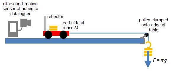
To verify the equation F = ma, where F is the resultant force on an object, m is the mass of the object and a is the acceleration, this is one of the ways to do so:
Equipment:
1. Motion Sensor
2. Datalogger
3. Cart with variable mass
4. End Stop
5. Pulley with clamp
6. Hanger Mass Set
7. String (about 1.2 m)
For a system of a cart of mass M on a horizontal track that is connected to a hanging mass m with a string over a pulley, the net force F on the entire system (cart and hanging mass) is the weight of hanging mass. F = mg (no friction assumed).
According to Newton’s Second Law, mg = (M+ m)a. We will try to prove experimentally that this is true in the video below.
In a recent IP3 class on Newton’s 2nd Law, the students were presented the “Elevator Problem” based on the THINK Cycle approach – a version of inquiry-based learning that was started in Temasek Junior College, Singapore.
The “Elevator Problem” is a physics phenomenon observed in an everyday experience that students can relate to quite easily. It is presented to our IP3 (K9 students) right after the introduction of Newton’s 2nd Law, with the students having a good understanding of the forces of weight and normal contact as well as what makes a resultant force.
TRIGGER
The THINK Cycle kicks off with a Trigger: a problem or phenomenon for which students have to solve or explain. In the “Elevator Problem”, the Trigger is the observation that as I stand on a bathroom scale in a lift going from one floor to another, the reading on the scale changes in such a way:
When the lift starts moving, the reading on the scale increases momentarily.
For most of the journey, the reading is constant.
When the lift is stopping, the reading on the scale decreases momentarily
The video below (taken by myself) shows what happens:
The students are supposed to work in groups to explain this observation and hence, to deduce whether the elevator is on its way up or down.
HARNESS
In the Harness stage of the THINK Cycle, students would work in groups to answer some guiding questions to help them arrive at a conclusion:
What are the forces acting on the boy?
Which of these forces are constant and which can change?
How does the motion of the lift affect the changing force?
What force is the weighing scale showing?
I find that providing students with a small portable whiteboard or a few pieces of rough paper is necessary for them to represent their ideas in diagram form, especially when the objectives of this activity is best achieved with the help of free-body diagrams.
INVESTIGATE
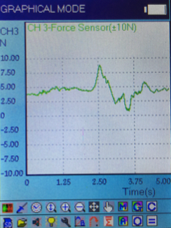
After coming up with a hypothesis based on their discussions, they will then seek to verify their hypothesis. Task number 2, which is for students to determine whether the elevator is going up or down, can be tested by hanging a 500 g mass on a force meter attached to a datalogger. We use the Addestation aMixer in our school, which is a handy portable datalogger with a plug-and-play range of user-friendly sensors. It gives us a graph that looks like that shown below when the mass is being pulled upwards, thus confirming that the movement of the elevator is also upward.
Variation of tension with time as the mass is pulled upwards.
The initial increase in tension acting on the mass is similar to that of the normal contact force on the man standing on the bathroom scale on the elevator. This is because both systems are accelerating upward.
The graph looks rather haphazard as the pulling is done manually and over a small height. By the time one pulls the mass up, he will have to decelerate already, which explains the dip in tension that follows right after the peak. Hence, we are unable to observe a stage where the tension is equal to weight, as we did for the scale in the elevator.
Nevertheless, students should be able to appreciate that a rise followed by a drop is observed for a mass being pulled upward.
NETWORK
For the sake of checking what the students have learnt collaboratively, each group is tasked to explain their observation and results on a A2-sized poster, with half the group staying at their own posters to answer questions while the other half going around to study the results from other groups. Their roles can be reversed after some time.
KNOW
In the final stage of our activity, the teacher will address the class and point out the common misconceptions that arose during the class discussions. For instance, many students are unaware that the upward force acting on the person standing on a weighing scale is the normal contact force and not the gravitational pull. This requires the teacher to introduce the terms “apparent weight” and “true weight” and making a distinction between the two.
Here are some interesting lecture demonstrations on adiabatic thermodynamic processes you can carry out. In an adiabatic process, there is no heat transfer between the system and other systems (including its environment.) According to the First Law of Thermodynamics (), where Q = 0, a compression of a gas which is associated with work being done on the gas will cause the internal energy and hence, the temperature of the gas to rise. On the other hand, when an expansion of a gas takes place, the gas will cool down.