12 Superposition

Pressure Variation in Stationary Sound Waves

For sound waves, we learnt that the compressions (position of maximum pressure) and rarefactions (minimum pressure) occur at the equilibrium position of the displacement of particles. This suggests that the pressure would vary the most in a stationary wave at the nodes of displacement. Right in the middle between two adjacent displacement nodes is the displacement antinode and we should expect the pressure variation to be the minimum there.

A displacement node is a pressure antinode.
A displacement antinode is a pressure node.

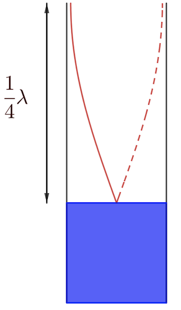
The standing waves associated with resonance in air columns can, therefore, be visualized in terms of the pressure variations in the column. Daniel A. Russell from The Pennsylvania State University made a wonderful animation showing how the variation of pressure occurs along an air column. (Link here)

It is a common misconception, even among physics teachers, that if a microphone is moved along the air column, it will pick up the loudest sounds at the displacement antinodes. However, according to Young & Geller (2007), College Physics 8th Edition, Pearson Education Inc. (pg 385), microphones and similar devices usually sense pressure variations and not displacements. In other words, the position within a stationary sound wave at which the loudest sound is picked up is at the displacement nodes which are the pressure antinodes.

Update: I made a GeoGebra interactive version of this animation of a stationary longitudinal wave.

Also check out my animation for a progressive longitudinal wave.

Single Slit Diffraction using Fingers

This demonstration requires no material other than your own fingers. Hold your index and middle fingers close to each other, leaving a small slit between them about 1 mm in width.

Look through the slit into a source of light such as the window or a lamp. You will need to look with one eye up close to the slit. Warning: do not look directly at the sun.

You will be able to see a number of vertical dark lines between the fingers.

diffraction and interference pattern,

Science Explained

So where do these vertical lines come from? They are dark fringes caused by destructive interference of light when it diffracts through your finger tips.

This phenomenon can be explained using Huygens’ principle. Huygens pictures every point on a primary wavefront as a source of secondary wavelets and the sum of these secondary waves determines the form of the wave at any subsequent time. Hence, each of these secondary wavelets can interference with one another.

Constructive interference takes place when the difference in path lengths between two coherent waves is an integer multiple of the wavelength. This is when the resultant wave is the brightest. Destructive interference occurs when that difference in path length is a half-integer of the wavelength (e.g. $\frac{1}{2}\lambda$, $\frac{3}{2}\lambda$, $\frac{5}{2}\lambda$, etc.) and gives a dark fringe.

The alternating bright and dark fringes is a diffraction pattern, which becomes observable by the eye looking through the slit.

Measuring Speed of Sound

Outline for Measuring the Speed of Sound Using a Tuning Fork and a Hollow Pipe Submerged in Water:

  1. Equipment Setup:
    • Obtain a tuning fork of known frequency and a hollow pipe that can be partially submerged in a column of water.
    • The pipe should be open at the top and closed at the bottom by the water surface.
  2. Strike the Tuning Fork:
    • Strike the tuning fork on a soft surface to make it vibrate. This produces a sound wave of a specific frequency, known as the fundamental frequency of the tuning fork.
  3. Submerge the Hollow Pipe:
    • Submerge the hollow pipe vertically in a large container filled with water. The length of the air column inside the pipe can be adjusted by raising or lowering the pipe in the water.
  4. Create Resonance:
    • Hold the vibrating tuning fork above the open end of the pipe. Slowly raise or lower the pipe in the water while listening for the loudest sound, which indicates resonance.
    • Resonance occurs when the length of the air column in the pipe is such that it forms a standing wave with the frequency of the tuning fork. This usually happens when the length of the air column is a quarter of the wavelength of the sound wave.
  5. Measure the Air Column Length:
    • When resonance is achieved (indicated by a significant increase in sound amplitude), measure the length of the air column from the water surface to the top of the pipe. This length corresponds to one-quarter of the wavelength of the sound wave in air.
  6. Calculate the Wavelength:
    • Multiply the measured length by 4 to determine the wavelength of the sound wave.
  7. Determine the Speed of Sound:
    • Use the formula Speed of Sound = Frequency × Wavelength ($v = f\lambda$) to calculate the speed of sound in air. The frequency is given by the tuning fork, and the wavelength is obtained from the previous step.

Explanation:

The speed of sound in air can be measured using the relationship between the frequency of the sound wave and its wavelength, which are connected by the speed of sound. When the tuning fork vibrates, it creates sound waves that travel through the air. When these waves enter the hollow pipe, they reflect off the water surface, and at certain lengths, they create a resonance condition, amplifying the sound. The resonant length corresponds to one-quarter of the wavelength because the pipe is effectively closed at the bottom (by the water), forming a node at the water surface and an antinode at the open end. By measuring this length and knowing the frequency of the tuning fork, the speed of sound can be calculated.