IP4 12 DC Circuits

DC Circuits Practice

The simulation below allows students to practise calculating potential differences and currents of a slightly complex circuit, involving three different modes that can be toggled by clicking on the switch.

Link: https://www.geogebra.org/m/jkckp9pr

Mode 1: Two Resistors in Series

When resistors \( R_1 \) and \( R_2 \) are connected in series, the total resistance is simply the sum of the individual resistances:

\[ R_{\text{total}} = R_1 + R_2 \]

The current \( I \) through the circuit is given by Ohm’s Law:

\[ I = \frac{V_{\text{total}}}{R_{\text{total}}} = \frac{V_{\text{total}}}{R_1 + R_2} \]

where \( V_{\text{total}} \) is the total potential difference supplied by the source.

The potential difference across each resistor can be calculated using:

\[ V_1 = I \cdot R_1, \quad V_2 = I \cdot R_2 \]

Mode 2: \( R_1 \) and \( R_3 \) in Parallel, \( R_2 \) in Series

In this mode, resistors \( R_1 \) and \( R_3 \) are in parallel, and \( R_2 \) is in series with the combination. First, calculate the equivalent resistance of the parallel combination:

\[ \frac{1}{R_{\text{parallel}}} = \frac{1}{R_1} + \frac{1}{R_3} \]

Thus, the total resistance is:

\[ R_{\text{total}} = R_{\text{parallel}} + R_2 \]

The current through the circuit is:

\[ I = \frac{V_{\text{total}}}{R_{\text{total}}} \]

The potential difference across \( R_2 \) is:

\[ V_2 = I \cdot R_2 \]

Since \( R_1 \) and \( R_3 \) are in parallel, they share the same potential difference:

\[ V_1 = V_3 = V_{\text{total}} – V_2 \]

The current through each parallel resistor can be found using Ohm’s Law:

\[ I_1 = \frac{V_1}{R_1}, \quad I_3 = \frac{V_3}{R_3} \]

Mode 3: \( R_1 \) and \( R_2 \) in Series, \( R_3 \) in Parallel

Here, resistors \( R_1 \) and \( R_2 \) are connected in series, and the combination is in parallel with \( R_3 \). First, calculate the resistance of the series combination:

\[ R_{\text{series}} = R_1 + R_2 \]

Then, find the total resistance of the parallel combination:

\[ \frac{1}{R_{\text{total}}} = \frac{1}{R_{\text{series}}} + \frac{1}{R_3} \]

The total current is:

\[ I = \frac{V_{\text{total}}}{R_{\text{total}}} \]

The voltage across the parallel combination is the same for both branches:

\[ V_1 + V_2 = V_3 = V_{\text{total}} \]

The current through \( R_3 \) is:

\[ I_3 = \frac{V_3}{R_3} \]

The current through \( R_1 \) and \( R_2 \), which are in series, is the same:

\[ I_{\text{series}} = \frac{V_{\text{total}}}{R_1 + R_2} \]

The voltage across each series resistor is:
\[ V_1 = I_{\text{series}} \cdot R_1, \quad V_2 = I_{\text{series}} \cdot R_2 \]

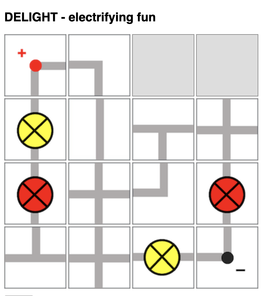
Delight – a web-based board game on electricity

I had previously shared about this physical board game that I designed to teach electricity concepts. Now, with ChatGPT’s help, I have managed to produce a simple implementation of the board game so that there is no need to print and cut out the pieces anymore.

However, the game is still unable to detect if the light bulb will light up and automatically change the image colour or add the scores. That will require further complex programming due to the many possible outcomes for this game.

https://physicstjc.github.io/sls/delight/index.html

The rules of the game are as such:

  1. Players will take turns to connect their own bulbs to the terminals while trying to sabotage their opponent’s bulbs.
  2. Players will take turns to place one piece on the 4-by-4 game board by clicking to select the electrical component and clicking on the square on the board to place it.
  3. Upon placing the piece, the player can also turn that piece in any orientation (by clicking on it) within the same turn.
  4. Players can choose to use up to two turns at any point in the game to rotate any piece that had been placed by any player.
  5. In other words, each player has 9 turns: 7 placement turns and 2 rotation turns.

At lower levels, students can compete to see who has the most lit bulbs. However, they will need to be able to identify which light bulbs are lit. Do watch out for short-circuits.

At higher levels, students can compete to see whose light bulbs has the most total electrical power, with some calculations involved.

Internal Resistance and Terminal Potential Difference

https://www.geogebra.org/m/puvfjxk5

This applet demonstrates how terminal potential difference (as measured by the voltmeter across the terminals of the battery) changes depending on :

  1. internal resistance r
  2. external resistance R
  3. emf E
  4. when a switch is turned on and off
<iframe scrolling="no" title="Internal Resistance and Terminal Potential Difference" src="https://www.geogebra.org/material/iframe/id/puvfjxk5/width/640/height/480/border/888888/sfsb/true/smb/false/stb/false/stbh/false/ai/false/asb/false/sri/false/rc/false/ld/false/sdz/false/ctl/false" width="640px" height="480px" style="border:0px;"> </iframe>

Potential Divider with Thermistor Applet

The wonderful thing about GeoGebra is that you can whip up an applet from scratch within an hour just before your lesson and use it immediately to demonstrate a concept involving interdependent variables. I was motivated to do this after trying to explain a question to my IP4 students.

The RGB colours of the thermistor reflects the temperature (red being hot, bluish-purple being cold)

https://www.geogebra.org/m/etszj23m

This was done to demonstrate the application of potential dividers involving a thermistor and a variable resistor. It can, of course, be modified very quickly to introduce other circuit components.

Videos on Series and Parallel Bulbs

These are two videos that I made on series and parallel bulbs. The second video is specially made to highlight the increase in brightness of the remaining bulbs when one or more bulbs is removed from its socket.

What students will learn in O levels is that the brightness of the bulbs will not change as the potential difference is a constant, being the emf itself.

Based on the conflict between what is taught and what is observed, students will be led to discuss the reason why.

If anyone is interested in getting the demonstration kit, do check out Funlearners.com.

Hidden Circuits Interactive

I made this interactive tool using javascript for the teaching of DC circuits for integration with SLS as part of the IP4 Physics blended learning experience in the upcoming weeks.

The intention of this interactive is for students to do a preliminary inquiry activity to exercise what they learnt about series and parallel circuits. They can be tasked to draw out what they think the circuit diagram will be like, either on Nearpod or SLS.

Students can even notice the differences in brightness under different conditions. Questions can be designed around this as well.

Previously we used to construct little boxes with wires hidden underneath. However, due to wear and tear and with Covid-19’s safe management measures, a digital version that can be accessed via the students’ mobile devices is more suitable.

Light bulb image is adapted from Good Ware from www.flaticon.com
Switch image is adapted from Those Icons from www.flaticon.com

For a direct link to this interactive, please go to: https://www.physicslens.com/wp-content/uploads/2022/04/index.html (updated link)

To obtain the zip file for upload into SLS as an interactive media object, click here.