This demonstration is called Newton’s nightmare because it involves the slow dropping of a magnet that seems to be inconsitent with gravitational acceleration.
Using the “CFILE” structure, we can explain how the magnet moves much slower in a metal pipe than when it is undergoing free fall (as in the PVC pipe, which serves as a control).
Now, the metal that we use cannot be ferromagnetic, or the magnet will not even drop at all. It will simply be attracted to the pipe and stick to it.
However, if another metal such as copper or aluminum is used, as the magnet moves through the pipe, different sections of the pipe will experience either a change (either decreasing or increasing) in magnetic flux. Sections of the pipe that the magnet has just gone through suffers a decreasing flux while those that the magnet are approaching gains magnetic flux.
By Faraday’s law, which states that an induced emf is proportional to the rate of change of magnetic flux linkage, emf and hence, current is induced within the pipes. These induced currents are called eddy currents.
By Lenz’s law, the induced currents tend to flow in a way so as to oppose the change causing it. The current in the sections of the pipe that the magnet is leaving will trying to attract the magnet while those that the magnet is approaching will try to repel the magnet.
The effect is that the magnet experiences a retarding magnetic force that acts against gravitational force, hence decreasing its downward acceleration.
I didn’t want to spend money on buying a piece of pyrolytic graphite and large neodymium magnets so I made do with what I have to make the following video. While diamagnetism is not in the A-level physics syllabus, it’s good for students to know that there are other classifications of magnetic materials.
What we study in our syllabus is ferromagnetism, which is exhibited by materials such as iron, cobalt and nickel. Some pencil leads are paramagnetic (weakly attracted to magnets) while others such as the one in the video are diamagnetic (repelled by magnets).
I bought my neodymium magnets from DX.com and the shipping to Singapore takes about 3 weeks, so you might want to factor that time in if you want to get some for your lessons. These magnets are great for other demonstrations such as homopolar motors and Newton’s nightmare.
Download Now

Delight by Tan Seng Kwang is licensed under a Creative Commons Attribution-NonCommercial-ShareAlike 3.0 Unported License.
An educational board game for 2 or any even number of players (in 2 teams) based on the concepts of current electricity. Targeted at high school / junior college physics students, Delight is a fun way of practising the use of physics concepts such as
- electrical power
- the potential divider rule.
- wires bypassing a device short-circuits it.
This game can be easily printed on A4 paper and the game pieces can be cut up for use.
Game Play
- This game is meant for 2 players or 2 teams of players. Each player/team has the following tiles:
- 2 x light bulbs
- 3 x T-shaped wires
- 2 x crossed wires
- The players will take turns to place the tiles on the board.
- Each new tile must have at least one wire connected to an existing wire on the board.
- The game will end when the last tile has been placed on the board.
- The person with the brightest bulb will win.In the event that there is an equal number of opposing bulbs of the same brightness, it will be considered a tie. If there are three bulbs of the same brightness, the one with two of these bulbs wins.
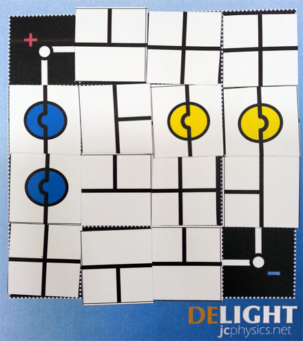
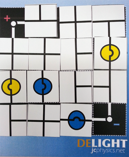
Test Yourself: Who is the winner for the games below?
GAME 1

GAME 2

Conditions for Using this Game
- Anyone can print and use this game for free as long as it is for educational or personal use. Any other reproduction or republishing of this material, in hard copy or electronic form, without written permission, is prohibited.
- If you would like to make a suggestion or an enquiry, please leave a comment below.
The Potential Divider Rule
Determining the relative brightness of light bulbs using the potential divider rule
How Internal Resistance affects brightness of light bulbs
