15. Electromagnetism

[accordions autoHeight=’true’]

[accordion title=”1. Definitions”]

  • The magnetic flux density at a point is defined as the force acting per unit current per unit length of the conductor when the conductor is placed at right angles to the field.
  • One tesla is the uniform magnetic flux density which, acting normally to a long straight wire carrying a current of 1 ampere, causes a force per unit length of 1 N m–1 on the conductor.

[/accordion]

[accordion title=”2. Magnetic Fields”]

  • The following are the vector symbols used in diagrams to represent the direction of vectors in 3 dimensional space:
    • : on the plane of the page
    • : into of the page
    • : out of the page
  • The following are some important points to take note when representing a magnetic field by magnetic field lines:
    • Magnetic field lines appear to originate from the north pole and end on the south pole.
    • Magnetic field lines are smooth curves.
    • Magnetic field lines never touch or cross.
    • The strength of the magnetic field is indicated by the distance between the lines – closer lines mean a stronger field.

[/accordion]

[accordion title=”3. Force on a Current-Carrying Conductor in a Magnetic Field”]

  • When a wire of length l carrying a current I lies in a magnetic field of flux density B and the angle between the current I and the field lines B is θ, the magnitude of the force F on the conductor is given by F=BIlsinθ.
    magnetic force
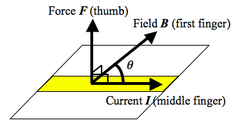
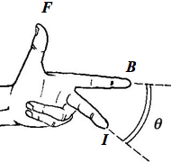
  • The directions of the vectors can be recalled by using the Fleming’s Left-Hand Rule.
    Fleming's Left-Hand Rule

[/accordion]

[accordion title=”4. Force on a Moving Charge in a Magnetic Field”]

  • A charge q travelling at constant speed v at an angle theta to a magnetic field of flux density B experiences a force F=Bqvsinθ.

[/accordion]

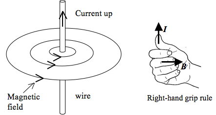
[accordion title=”5. Magnetic fields of current-carrying conductors”]

  • Long straight wire
    Right-Hand Grip Rule
  • Flat circular coil
  • Solenoid

[/accordion]

[accordion title=”6. Ferromagnetic Materials”]

[/accordion]

[accordion title=”7. Force between Two Parallel Current-Carrying Conductors”]

  •  Like currents attract and unlike currents repel.

[/accordion]

[/accordions]

Single Slit Diffraction using Fingers

This demonstration requires no material other than your own fingers. Hold your index and middle fingers close to each other, leaving a small slit between them about 1 mm in width.

Look through the slit into a source of light such as the window or a lamp. You will need to look with one eye up close to the slit. Warning: do not look directly at the sun.

You will be able to see a number of vertical dark lines between the fingers.

diffraction and interference pattern,

Science Explained

So where do these vertical lines come from? They are dark fringes caused by destructive interference of light when it diffracts through your finger tips.

This phenomenon can be explained using Huygens’ principle. Huygens pictures every point on a primary wavefront as a source of secondary wavelets and the sum of these secondary waves determines the form of the wave at any subsequent time. Hence, each of these secondary wavelets can interference with one another.

Constructive interference takes place when the difference in path lengths between two coherent waves is an integer multiple of the wavelength. This is when the resultant wave is the brightest. Destructive interference occurs when that difference in path length is a half-integer of the wavelength (e.g. 12λ, 32λ, 52λ, etc.) and gives a dark fringe.

The alternating bright and dark fringes is a diffraction pattern, which becomes observable by the eye looking through the slit.

Ionisation of Air to Remove Static Electric Charges

Materials

  1. Wool
  2. PVC pipe or plastic comb
  3. String
  4. Lighter

Procedure

  1. Hang the string from an elevated position. Leave the bottom end free.
  2. Rub the PVC pipe with wool. This deposits negative charges, or electrons, onto the surface of the PVC pipe.
  3. Place the side of the pipe that is rubbed near the string. You should notice the string being attracted  towards the PVC pipe.
  4. Holding the PVC pipe still while attracting the string, light a flame using the lighter and place it in between the string and pipe. You should observe the string falling back to its original position.

Science Explained

When air is ionised with the help of a flame, it serves as a conducting medium through which static electric charges can escape from a surface.

Magnetic Shielding

Materials

  1. Bar magnet
  2. Paper clip (stainless steel)
  3. Plastic clipboard
  4. Steel bookend

Procedure

  1. Before the demonstration, make sure that the paper clip is not already magnetised by touching it with the steel bookend. If it gets attracted to the bookend, get a new paper clip.
  2. For the demonstration, first show that the paper clip can be picked up by a bar magnet in direct contact.
  3. Next, place the bar magnet on the plastic clipboard and try to pick up the paper clip with the clipboard in between them. Show the audience that the paper clip is attracted.
  4. Finally, place the bar magnet on the steel bookend and attempt to pick up the paper clip with the bookend between them. The paper clip will not be picked up.

Science Explained

Iron and steel are examples of ferromagnetic materials that have their magnetic domains aligned with an external magnetic field when placed in that field. This strengthens the magnetic field but also serves to concentrate the field lines within the ferromagnetic material itself, such that very little of the magnetic field penetrates the “shield”.


Heat Capacity of Water

Water has a high specific heat capacity of about 4200 J kg-1 K-1. When a little bit of water is placed in a balloon, it is able to absorb a significant amount of heat from a candle flame and hence prevent the balloon from bursting.
Materials
  1. Two balloons
  2. Two candles
  3. Lighter
Procedure
  1. In this demonstration, one balloons is filled with about 3 tablespoons of water and then inflated.
  2. Another balloon is inflated to the same size as the first to serve as a control.
  3. Both balloons are then placed vertically over two identical candles. Adjust the balloons such that the distance from balloon to candle is the same for both setups. You can use retort stands to clamp the balloons in place if you have them.
  4. Light the candles with the balloons temporarily removed. The flames will have to touch the bottom of the balloon when they are placed back over the candles.
  5. Observe the balloon without water burst first.
  6. The air gushing out from the exploding balloon may put out the other candle.
  7. If you like, you can keep the balloon with water over the flame for a longer duration. The balloon still will not burst until a long time later.

Homopolar Motor 2

This video demonstrates how a simple homopolar motor is made using a screw and a small neodymium magnet. The simplest possible motor one can make, it can be used to teach concepts at various levels. For lower secondary students, they can learn about conversion of energy forms while upper secondary students can learn about magnetic forces and Fleming’s left-hand rule.

Materials

  1. 10 cm wire
  2. 1.5 V battery
  3. iron screw
  4. neodymium magnet

Procedure

  1. Attach the neodymium magnet to the head of the screw.
  2. Attach the tip of the screw to one end of the battery such that the screw hangs below the battery. The screw will remain attached to the battery as the magnetic force from the neodymium holds them together.
  3. Hold one end of the wire on the top terminal of the battery and allow the other end of the wire to touch the side of the screw or the magnet. Watch the screw spin.

(Link: Alternative design for the homopolar motor)