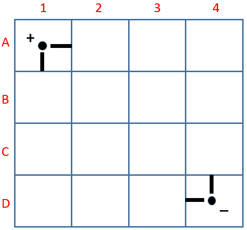
Using a neodymium magnet, some paper clips and a battery, you can demonstrate the magnetic force acting on a current-carrying wire while recalling Fleming’s left-hand rule. Using the same frame constructed in the previous video, you just need to add a wire with a few bends in between to create a U-shape in the middle as shown in the picture below. A small piece of insulating tape (you can use any adhesive tape) is added to one end of the wire to show the original dangling position of the U-shape before current flows through it. Be sure to leave some space at the end with the insulating tape for you to switch on and off the current by pushing that end in and out.
With the south pole facing up and the current flowing from right to left, the magnetic force acts towards you.When the insulating tape touches the paper clip, current stops flowing and there is no magnetic force.With the south pole facing up and the current flowing from right to left, the magnetic force acts away from you.
Using material that is easily available, you can build a simple homopolar D.C. motor (one that uses a single magnetic pole. I made the video above to help you do so.
The material used are as follows:
insulated copper wire
paper clips
neodymium magnet
1.5V AA battery
plastic or wooden block (I used a 4×2 Lego block)
scissors
permanent marker
adhesive tape
The steps involved are:
Attaching the magnet on the side of the battery using a long piece of adhesive tape and sticking both of them onto the Lego block. The polarity of the magnet does not matter.
Next, we need to shape one end of each paper clip so as to make it longer and to make a small loop at the top. The paper clips are then fixed on the ends of the battery using adhesive tape.
Coiling wire can be done with the help of a round cylindrical object such as a marker. Roughly 10-15 coils will do.
The ends of the wire can used to bundle the coils together. Make sure they are tied up tightly.
Since we are using an insulated wire (otherwise the current will just go straight from one paper clip to another without passing through the coils), we need to scrape of the insulation at the ends using either sandpaper or the edge of a pair of scissors.
Using a permanent marker, we can colour one side each end in order to insulate that side. This will prevent current from flowing through the loops for half of every cycle. It has the same effect as that of a commutator.
Finally, we will mount the coils onto the two paper clips and allow the motor to spin.
Do take note that the motor should not be left connected to the battery for too long as it will drain the battery very quickly and generate a lot of heat in the process.
How this can be used for the O-level/A-level syllabus
Teachers can use this as a demonstration that shows the motor effect of a current in a wire placed in a magnetic field, as well as to apply Fleming’s left-hand rule.
One can also make an second coil without insulating half the surface of the points of contact with the paper clips to show the importance of the commutator in a DC motor. The coil will simply oscillate to and fro due to the change in direction of the magnetic force on the lower half of the loop every half a turn.
I made this rather simple video this morning showing a physics demonstration on the effect of magnetic shielding. A paper clip is shown to be attracted to a magnet. A series of objects are placed in between, such as a plastic ruler, a steel ruler, a steel bookend, and some coins of different alloys.
It is interesting to note the types of material that provide magnetic shielding and those that do not. There is even a distinction between the types of steel, which is an alloy containing iron. Ferritic steel is magnetic while austenitic steel is not.
The theory behind magnetic shielding is that the flat magnetic material will direct the field lines of the magnet along its plane instead of allowing them to pass through, thus depriving the paper clip of a strong enough magnet field to keep it flying.
This simulation traces the flux linkage and corresponding emf generated by a rectangular coil rotating along an axis perpendicular to a uniform magnetic field. One is able to modify the angular frequency to see the effect on the frequency and peak emf generated.
This simulation is really more of an animation that allows students to apply Fleming’s left hand rule on a line of electrons along a conductor cutting a magnetic field in order to appreciate how emf is generated.
I modified “DeLight”, the board game that I designed a few years back into a worksheet version (for small groups) as well as a powerpoint version (that teacher can facilitate as a class activity, pitting half the class against another).
The objectives of the game is to reinforce concepts related to D.C. Circuits such as:
Sum of potential difference (p.d.) across parallel branches of a circuit is the same.
P.d. across a device is given by the ratio of resistance of device to total resistance multiplied by emf (potential divider rule)
Brightness of light bulb depends on electrical power
Current can bypass a device via a short-circuiting wire.
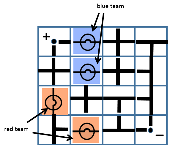
The worksheet and powerpoint slides contain a few examples that allow discussion on the above concepts based on some possible gameplay outcomes. For example, the following is a game where the blue team wins because the p.d. across each blue light bulb is twice that of the p.d. across each red light bulb.
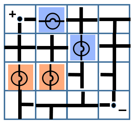
In the following scenario, the game ended in a draw. Students may not be able to see it immediately, but the blue light bulb with a vertical orientation is actually short-circuited by the vertical branch on its right.
Feel free to use and/or modify the game to suit your own class needs.